
ASTROPCB JOURNAL / MANUFACTURING
One revision. Clear requirements.
A board package ready for review.
What files do you need for PCB fabrication?
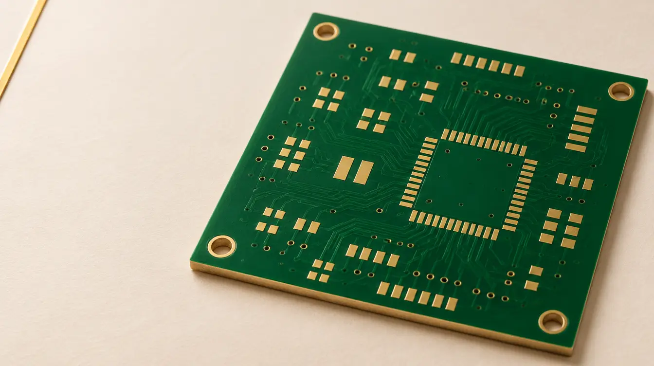
A PCB fabrication release should include board-layer data, drill and route data, an unambiguous board outline, and fabrication requirements covering stackup, material, thickness, copper, finish, and hole treatment. Keep every file at the same approved revision. For assembled boards, add the bill of materials, component placement data, and assembly instructions.
A useful PCB release package answers two questions: what geometry should the manufacturer build, and which requirements must the finished board meet? Treat the archive as an engineering handoff. The checklist below is a recommended release workflow; confirm the accepted formats and required deliverables with your manufacturer before ordering.
PCB fabrication files checklist
Use this table to review the archive before requesting a PCB quote. Each acceptance check is a practical handoff recommendation, not a universal manufacturing specification.
| Deliverable | What to include | Release check |
|---|---|---|
| Layer data | Copper layers, solder mask, and legend where used | Identify layer function and order; confirm the exported revision. |
| Board outline and routing | Finished perimeter, internal cutouts, slots, and mechanical notes | Make the intended finished edge unambiguous. |
| Drill data | Hole locations and sizes, with plating and span requirements | Distinguish plated and non-plated features; identify blind or buried spans. |
| Fabrication drawing | Dimensions, tolerances, finish, hole treatment, and acceptance requirements | Resolve conflicts with the order form and stackup. |
| Stackup | Layer sequence, material requirements, dielectric construction, and copper requirements | Record which values are fixed and which need fabricator approval. |
| Impedance requirements, if applicable | Target, tolerance, layer, reference plane, and relevant trace geometry | Agree on the production stackup and any permitted geometry changes. |
| Release manifest | Board identifier, revision, archive contents, quantity, and approval contact | Remove superseded outputs and mark unresolved questions. |
| Assembly package, if applicable | BOM, placement data, assembly drawings, and special instructions | Match reference designators, variants, and revision to the board package. |
What Gerber files describe—and what to document alongside them
Ucamco, the Gerber format developer, describes Gerber layer files as representing copper, solder mask, legend, and drill and route data. Attributes add information about those images, while the Gerber Job file can carry fabrication characteristics such as thickness and finish. These are different parts of the handoff, so review both geometry and build requirements. [1]
Our recommended approach is to give each required layer a clear function and include a short manifest explaining the package. If your CAD tool produces a Gerber Job file, check its values against the drawing and order requirements before including it. Do not leave conflicting thickness or finish instructions for the fabricator to interpret.
KiCad documents Gerber plotting, drill output, IPC-2581, ODB++, and component placement outputs separately. Its output options provide a useful reminder that an export command does not, by itself, define the complete order package. Confirm which format the receiving manufacturer accepts and avoid supplying competing versions of the same board. [2]
Review holes, slots, and board edges together
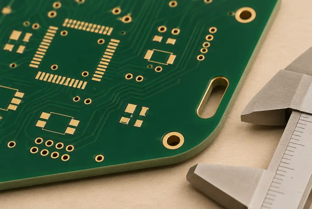
Make a mechanical review pass before release. Overlay the drill data and board outline with the copper layers, then check connector holes, mounting holes, cutouts, and slots against the intended design. Record the required finished dimensions and tolerances in the fabrication requirements.
For a slotted feature, explicitly state whether the slot is plated and where its finished boundary belongs. For blind and buried vias, identify the connected layer span. For via-in-pad structures, document the required filling and capping treatment instead of assuming the hole location communicates the complete construction.
If these features are part of your board, use the via-in-pad capability page as a starting point for the manufacturing discussion, then request confirmation for your specific construction.
Turn stackup and impedance into explicit requirements
For a multilayer release, provide a proposed layer sequence and clearly identify material restrictions, finished board thickness, copper requirements, and any controlled-impedance circuits. If alternatives are acceptable, describe what needs approval before substitution rather than using a broad instruction such as “equivalent material allowed.”
Use an impedance table that a reviewer can trace back to the layout. For example, an illustrative row might read: “Differential pair; L3 referenced to L2/L4; 100 Ω target; tolerance to be agreed; production geometry subject to written approval.” This is an example of documentation structure, not a recommended target for every interface. Your design requirements must determine the actual values.
Separate nominal design values from approved production values. Ask the fabricator to return the proposed stackup and identify any requested trace-width or spacing changes. Review those changes before authorizing manufacture. AstroPCB’s controlled impedance page provides a relevant next step for that discussion.
Keep fabrication and assembly deliverables distinct
When ordering assembly, add a BOM, placement data, and assembly drawings to the release. In the BOM, specify the intended manufacturer part numbers and document substitution rules. In the placement and drawing review, check board side, reference designators, component orientation, and variant-specific do-not-populate instructions.
KiCad’s placement-file documentation describes position, orientation, and board-side information for components. Use that exported information as one input to the assembly review, alongside the BOM and drawings. [2] Ask your assembler to confirm its coordinate-origin and rotation conventions before treating the placement file as ready for production.
Run a final release check before sending the archive
- Freeze the revision. Export all deliverables from the same approved design state.
- Inspect the outputs. Open the exported manufacturing files in a viewer and compare the layer order, outline, drills, and critical features with the design.
- Reconcile the requirements. Compare the drawing, stackup, job file, and order form for conflicting instructions.
- Record open items. Identify every decision still awaiting approval and state that production release depends on resolving it.
- Archive the approved package. Keep the exact files and written clarifications used to authorize production.
A simple manifest can begin with “Board: controller-main; revision: C; purpose: quotation and DFM review; production release: pending.” After the outstanding questions are closed, update the release status and preserve the approved archive. Use your organization’s actual revision scheme and approval process.
Frequently asked questions
Are Gerber files enough to order a PCB?
Review the complete package, including hole and routing information plus fabrication requirements. Gerber supports layer data and related attributes, and a Gerber Job file can describe characteristics such as thickness and finish. Confirm which deliverables your manufacturer requires. [1]
Do I need a BOM for bare-board fabrication?
For this checklist, the BOM belongs in the assembly package. For a bare-board order, focus the handoff on board data and fabrication requirements, and confirm the supplier’s intake requirements before submission.
Should I send Gerber, ODB++, and IPC-2581 together?
Agree on the primary manufacturing format with the receiving team. If you provide additional formats for reference, label them clearly and verify that they represent the same revision. Do not ask the manufacturer to choose between inconsistent releases.
What should I include for controlled impedance?
Document the target and tolerance, signal layer, reference plane or planes, relevant geometry, and proposed stackup. Ask the manufacturer to confirm the production construction and obtain approval for any required layout changes.
How should I handle a file change after quoting?
Issue an identified revision and describe the change. Ask the manufacturer to reconfirm the quote, schedule, and manufacturing review as applicable, then preserve the exact package approved for production.
Make the next handoff a clear one.
Share your board revision, release files, quantity, and open technical questions with AstroPCB. Start with an engineering review before authorizing production.
Technical references
[1] Ucamco, Gerber format overview: layer data, attributes, and Gerber Job information.
[2] KiCad, PCB Editor reference manual, generating outputs and component placement files.
Visuals: AI-generated editorial illustrations created with Higgsfield. They are illustrative, not production drawings or photographs of a specific AstroPCB product.