
Flex PCB manufacturer · Flexible circuit boards
Flex PCB Manufacturer for Flexible Circuit Boards
Single-sided, double-sided and multilayer polyimide flex circuits with coverlay, stiffeners and controlled impedance. Each design is reviewed against how the circuit bends in your product.
- Flex copper layers
- 1–6+
- Polyimide base film
- 12.5–50 µm
- Thinnest single-layer flex
- 0.05 mm
- Impedance tolerance
- ±8%
What is a flex PCB
Flexible circuit boards, explained.
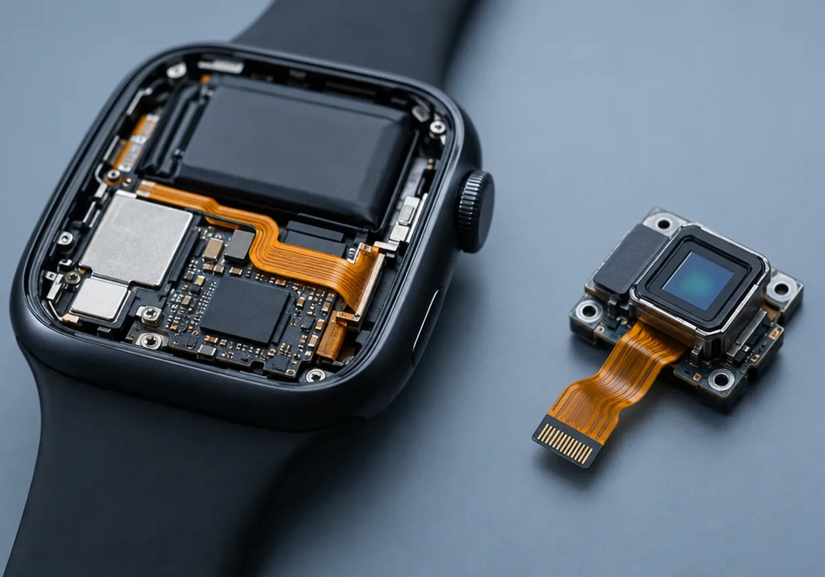
A flex PCB (flexible printed circuit, FPC) is a circuit built on a thin polyimide film instead of rigid FR-4, so it can bend, fold or move. Flexible circuit boards replace wire harnesses, ribbon cables and connectors where space is tight, weight matters or the circuit must flex during use.
Copper traces are bonded to polyimide with or without adhesive, then protected by a polyimide coverlay instead of solder mask, because coverlay keeps its integrity through repeated bending. Stiffeners are added only where connectors or components need support.
As a flex PCB manufacturer, AstroPCB reviews every design from the mechanical use case: where the circuit bends, how tightly, how often and what it connects to. Then we choose copper type, adhesive system, coverlay openings and stiffeners to match.
- Thin, light and able to fit three-dimensional enclosures
- Fewer connectors and solder joints, so fewer failure points
- Repeatable routing and impedance compared with hand-built cables
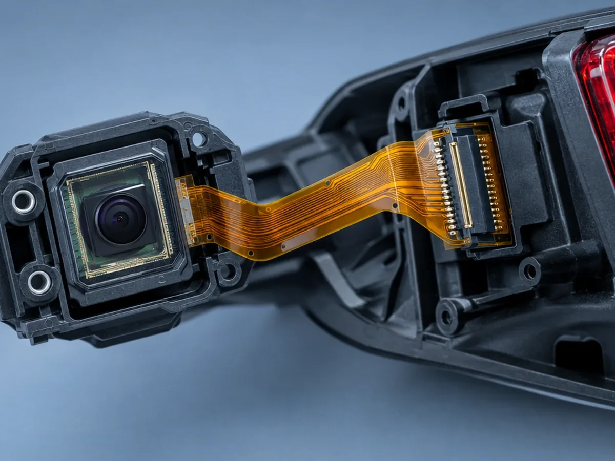
A flex circuit folded to its installed shape.
Why AstroPCB
Why choose AstroPCB as your flexible PCB manufacturer.
A flexible PCB manufacturer has to design for motion, not just for the netlist. We review bend zones, copper type, coverlay openings and stiffeners against how your flexible circuit board actually moves before it is built.
- Single-sided to multilayer flex, adhesiveless or adhesive-based, RA or ED copper
- Bend-zone and stiffener review included with every flex quote
- Engineering since 2008: 1,000+ engineers and 30+ partner factories in Shenzhen, Xi’an, Chengdu and Hangzhou
- Written DFM review on every order, prototype or production, before fabrication starts
- 99.6% on-time delivery across the partner factory network
- From 1 piece to volume with the same stack-up and process controls
- IPC Class 2 by default, Class 3 on request, with inspection records and batch traceability
- Fabrication plus assembly: component sourcing, SMT and tracked worldwide shipping
Flex PCB capabilities
Flex PCB manufacturing capabilities.
Every flex quote includes an engineering review of bend zones, stiffeners and coverlay openings.
| Parameter | AstroPCB capability |
|---|---|
| Flex constructions | Single-sided, double-sided and multilayer flex; rigid-flex available |
| Polyimide base film | 12.5, 25 and 50 µm (0.5, 1 and 2 mil) |
| Thinnest construction | Single-layer flex from about 0.05 mm total; typical 2-layer flex 0.1–0.2 mm with coverlay |
| Copper | Rolled-annealed (RA) for dynamic flex; electrodeposited (ED) for static designs |
| Bonding system | Adhesiveless or adhesive-based (acrylic / epoxy) laminates |
| Protection | Polyimide coverlay; flexible solder mask for fine openings |
| Stiffeners | FR-4, polyimide and stainless steel |
| Min. line / space | 50 / 50 µm |
| Controlled impedance | ±8% with confirmed stack-up; hatched planes supported |
| Surface finishes | ENIG (most common), immersion tin, immersion silver, OSP, soft / hard gold fingers |
| High-frequency flex | LCP flex materials available for higher-frequency designs |
| Acceptance standard | IPC-6013 Class 2 by default, Class 3 on request |
Flex PCB types
Choose the flex construction your product needs.
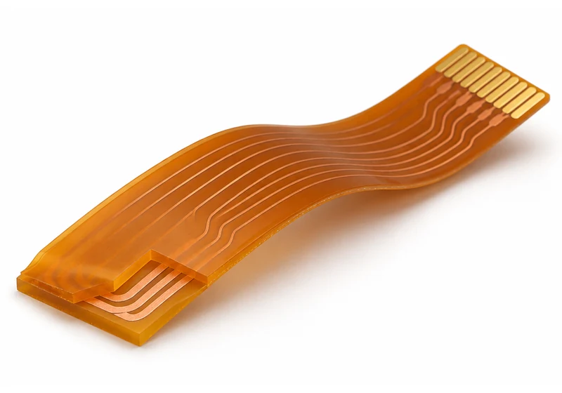
Single-sided flex
One copper layer on polyimide with coverlay. It is the thinnest and most flexible construction, and the best choice for dynamic flexing, LED strips, sensors and battery connections.
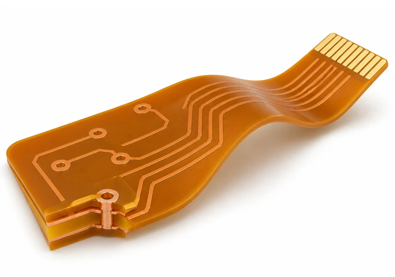
Double-sided flex
Two copper layers joined by plated through-holes, which allows ground planes, impedance-controlled differential pairs and moderate component density.
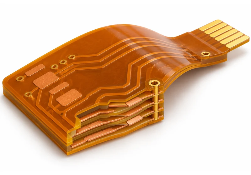
Multilayer flex
Three or more copper layers for dense interconnects. It is thicker and stiffer, so the bend radius grows. Combine it with rigid sections in a rigid-flex PCB when you need component-dense areas.
Flex PCB design guidelines
Flex design rules that prevent cracked copper.
| Flex construction | Static bend | Dynamic bend |
|---|---|---|
| Single-layer flex | ≈ 6× thickness | ≈ 100× thickness |
| Double-layer flex | ≈ 12× thickness | Avoid where possible |
| Multilayer flex | ≈ 24× thickness | Not recommended |
- Route traces perpendicular to the bend and use curved corners, never 90° angles, in flex areas.
- Stagger traces on double-sided flex so top and bottom conductors do not overlap in the bend.
- Keep vias and pads out of bend zones; add teardrops and anchoring spurs to flex pads.
- Use hatched copper planes where the flex must stay flexible, and include them in impedance calculations.
- Specify stiffeners behind connectors and ZIF tails: material, thickness and location.
- Use RA copper and adhesiveless polyimide for dynamic flex.
Read more in our polyimide PCB guide.

Stiffener supporting a ZIF connector tail.
Flex materials
Polyimide, copper and coverlay options.
Polyimide laminates
Adhesiveless polyimide offers a thinner profile, better flex life and higher temperature performance. Adhesive-based laminates are a cost option for static flex.
Polyimide materialRA vs ED copper
Rolled-annealed copper has an elongated grain that resists fatigue, which makes it the choice for dynamic flex. ED copper works for flex-to-install designs.
Copper thickness guideCoverlay & finishes
Polyimide coverlay protects traces through bending. ENIG is the most common flex finish because it is flat and solders well.
Surface finishesWhere flex PCBs are used
Industries that use flexible circuit boards.

Medical & wearables
Patches, hearing aids, catheters and monitors that need thin, light and biocompatible-friendly constructions.
Medical PCB
Automotive & EV
Camera modules, lighting and battery-module interconnects exposed to vibration and temperature cycling.
Automotive PCB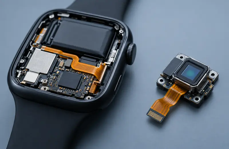
Consumer & industrial
Displays, cameras, printers, robotics and sensors where cables are replaced by a single flexible circuit.
All industriesFlex PCB cost
What drives flex PCB cost.
- Layer count and single- vs double-sided construction
- Adhesiveless vs adhesive-based polyimide
- RA vs ED copper and copper weight
- Stiffeners: count, material and bonding
- Coverlay openings and fine-pitch pad areas
- Panel utilization of the flex outline
- Impedance control and finish (ENIG, gold fingers)
- Quantity and IPC-6013 class
Send your files for a firm price. We will show where a simpler construction meets the same bend requirement.
Request a flex quote
What to include in your flex PCB RFQ.
- Gerber, ODB++ or IPC-2581 data and fabrication drawing
- Outline with flex, stiffener and bend areas marked
- Bend radius, angle and static or dynamic use
- Copper type (RA/ED) and adhesive system preference
- Coverlay openings and connector / ZIF details
- Impedance requirements and reference planes
- Finish, IPC class and quantity
- Assembly needs: see PCB assembly
FAQ
Flex PCB questions, answered.
What is a flex PCB?
A flex PCB, or flexible printed circuit, is built on thin polyimide film instead of rigid FR-4, so it can bend, fold or flex during use. It replaces cables, harnesses and connectors in compact products.
What is the difference between a flex PCB and a rigid-flex PCB?
A flex PCB is flexible throughout and usually connects to rigid boards with connectors. A rigid-flex PCB laminates rigid multilayer sections and flex circuits into one board, with no connectors between them. See rigid-flex PCB.
What is the thinnest flex PCB you can make?
Single-layer flex can be as thin as about 0.05 mm (2 mil) using adhesiveless polyimide. Typical double-sided flex is 0.1–0.2 mm including coverlay.
What is the minimum bend radius for a flex PCB?
Common IPC-2223 starting points for static bends are about 6× thickness for single-layer, 12× for double-layer and 24× for multilayer flex. Dynamic flex needs about 100× with single-layer RA copper. We confirm the radius in DFM.
Static vs dynamic flex: what changes?
Static (flex-to-install) circuits bend once during assembly. Dynamic circuits flex repeatedly in use, which calls for single-layer construction, rolled-annealed copper, adhesiveless polyimide and a larger bend radius.
Can flex PCBs carry high-speed or RF signals?
Yes. Polyimide has a Dk around 3.4 at 1 GHz and supports controlled impedance to ±8%. For higher frequencies, LCP flex materials are available.
What surface finishes are available for flex?
ENIG is the most common. Immersion tin, immersion silver, OSP and soft or hard gold for connector fingers are also available.
Do you assemble flex PCBs?
Yes. Components are placed on stiffened areas using carriers or fixtures. See PCB assembly services.
Ready when your files are
Send your flex outline and bend drawing for review.
Upload Gerber, ODB++ or IPC-2581 data. Every quote includes a written engineering DFM review, typically within one business day.