
PTFE PCB · Teflon PCB
PTFE PCB & Teflon PCB Fabrication
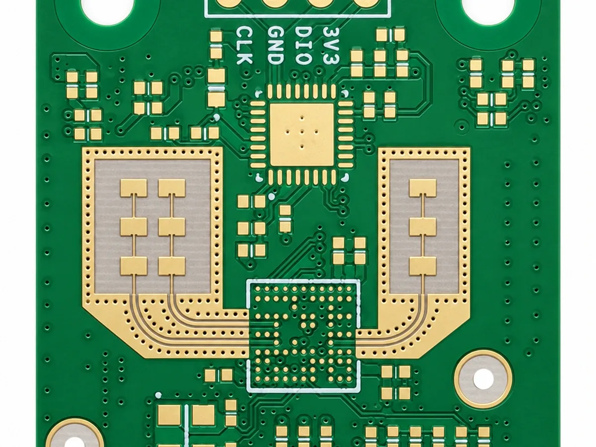
PTFE (Teflon) laminates with Dk about 2.1–2.2 and Df below 0.001 for microwave and mmWave boards: 24/77 GHz radar, 28/39 GHz 5G, satellite links and precision test equipment.
- Dk (RT/duroid 5880)
- ≈2.2
- Df @ 10 GHz
- 0.0009
- Moisture absorption
- ≈0%
- Radar capable
- 77 GHz+

What is a PTFE PCB
PTFE (Teflon) PCBs, explained.
A PTFE PCB (Teflon PCB) is built on polytetrafluoroethylene-based laminate, with Dk around 2.1–2.2 and Df below 0.001 at 10 GHz. That gives the lowest dielectric loss of any PCB substrate, which makes it the baseline for millimeter-wave circuits where every tenth of a dB counts. “Teflon” is a trade name for PTFE, so a Teflon PCB and a PTFE PCB are the same thing.
We build PTFE boards on Rogers RT/duroid, Taconic and other PTFE systems for radar, satellite, 5G mmWave, test equipment and defense applications, as all-PTFE constructions or hybrids with FR-4.
When PTFE is necessary
When PTFE is necessary.
Choose PTFE when frequency, trace length and loss budget cannot be met with a cheaper laminate. Below about 5 GHz, Rogers 4350B usually performs well enough at much lower cost and with easier fabrication. Between 5 and 15 GHz the choice depends on the loss budget. Above 15 GHz, and especially at 24 and 77 GHz automotive radar, 28/39 GHz 5G and 60 GHz V-band, PTFE is often required because loss on any other material exceeds the link budget.
PTFE also has essentially zero moisture absorption, against about 0.02–0.06% for Rogers hydrocarbon laminates and 0.1–0.3% for FR-4. For outdoor base stations, marine electronics and under-hood automotive hardware that see humidity cycling, that gives the most stable electrical performance.
Laminate systems
Common PTFE laminate systems.
| Laminate | Dk | Df @ 10 GHz | Use |
|---|---|---|---|
| Rogers RT/duroid 5880 | 2.20 | 0.0009 | Benchmark low-loss microwave, DC–77 GHz+ |
| RT/duroid 5870 | 2.33 | 0.0012 | Slightly higher Dk, low loss |
| RT/duroid 6002 | 2.94 | 0.0012 | Ceramic-filled, stable Dk, low CTE |
| RT/duroid 6010 | 10.2 | ≈ 0.0023 | Miniaturized patches and filters |
| Taconic RF-35 / TLY series | 2.2–3.5 | low | Alternative PTFE systems, antenna and radar |
The choice between Rogers and Taconic often comes down to the exact Dk and thickness you need, regional availability and cost. We confirm stock and lead time at quote, because some PTFE cores are made to order.
Wangling F4B
Wangling F4B PTFE laminates.
Wangling (Taizhou Wangling) F4B laminates are woven-glass PTFE copper-clad boards widely used for antennas, power dividers and base-station RF. The F4B and F4BM families cover a Dk range of roughly 2.2 to 3.5 (typical values; confirm with the Wangling datasheet), and F4BME adds a reverse-treated copper option. They are a cost-effective PTFE choice when the design does not call out a Rogers or Taconic part number.
| Grade | Dk (typical) | Typical use |
|---|---|---|
| F4B | ≈ 2.2–2.65 | Antennas, feed networks |
| F4BM | ≈ 2.2–3.5 | RF boards needing tighter Dk |
| F4BME | ≈ 2.2–3.5 | Lower conductor loss, mmWave-adjacent designs |
Comparison
PTFE vs other RF laminates.
| Property | PTFE (RT/duroid 5880) | Rogers RO4350B | FR-4 |
|---|---|---|---|
| Dk | 2.20 | 3.48 | 4.0–4.8 |
| Df @ 10 GHz | 0.0009 | 0.0037 | ≈ 0.02 |
| Moisture absorption | ≈ 0.02% | ≈ 0.06% | 0.1–0.3% |
| Processing | Special (plasma/etch, bonding films) | Standard FR-4 | Standard |
| Relative material cost | Highest | Medium | Lowest |
Fabrication challenges
Fabrication challenges with PTFE.
PTFE is soft and flexible, so it does not hold its shape like FR-4 during drilling and handling. Drill entry and exit conditions, feeds and speeds must be tuned to avoid smear, burrs and delamination. Before plating, hole walls need sodium-naphthalene etch or plasma treatment, because PTFE does not bond to electroless copper the way glass-epoxy does.
Multilayer PTFE needs precise press temperature and pressure. PTFE-to-PTFE bonding uses fusion bonding or specialized bondplies, and PTFE-to-FR-4 bonding uses compatible prepreg systems that bridge differences in CTE and bonding chemistry. Dimensional movement during lamination is larger than with FR-4, so scaling and registration are set specifically for PTFE.
- Optimized drilling to avoid smear
- Plasma or sodium etch for hole-wall activation
- PTFE-compatible bondplies for multilayer
- Scaling compensation for dimensional movement
- Microsection of plated holes and bond lines
Hybrid stack-ups
Hybrid PTFE/FR-4 stack-ups.
Many RF designs put PTFE only on the RF signal layer, for antenna elements and the RF front end, and bond it to FR-4 cores for digital control, power and mechanical support. That captures PTFE’s performance where it matters while keeping material cost manageable. We manage CTE matching, the bonding process and impedance modeling across the material transition, and we verify the bond line by microsection.
| Layer | Material | Use |
|---|---|---|
| L1 | PTFE core (e.g. RT/duroid 5880) | Antenna elements, RF front end |
| L2 | Copper | RF ground |
| Bond | Compatible bondply / prepreg | Joins PTFE to FR-4 |
| L3+ | High-Tg FR-4 | Digital, power, control |
Design
Designing on PTFE.
PTFE’s low Dk makes 50 Ω lines wider. On 20 mil PTFE, a 50 Ω microstrip is roughly 55–60 mil wide, against about 44 mil on RO4350B. That lowers conductor loss and reduces sensitivity to etch tolerance, but it uses more area. At mmWave, copper roughness and surface finish become significant, so specify low-profile copper and immersion silver or ENEPIG on RF layers.
- Use datasheet design Dk at your frequency
- Prefer immersion silver / ENEPIG on RF layers
- Keep RF ground continuous; add via fences
- Model launches and transitions above ~20 GHz
- Check widths with the impedance calculator
Cost
Why PTFE boards cost more.
PTFE laminates cost several times more than FR-4 because of the fluoropolymer raw material and the specialized processing: plasma treatment, special bondplies, slower drilling and tighter handling. Using PTFE only on the RF layers of a hybrid stack-up is the most effective way to control cost. If your design works at the frequency on RO4350B or RO4003C, that is usually cheaper and faster to build.
FAQ
Material questions.
Is a Teflon PCB the same as a PTFE PCB?
Yes. Teflon is a brand name for PTFE; both terms describe the same class of laminates.
What is the Dk of PTFE?
About 2.1–2.2 for glass-reinforced PTFE such as RT/duroid 5880; ceramic-filled grades range from about 2.9 to 10.2.
Why are PTFE PCBs so expensive?
Fluoropolymer material costs more, and fabrication needs plasma or sodium etch, special bondplies, careful drilling and dimensional compensation.
What frequency can PTFE PCBs support?
Well above 77 GHz; RT/duroid 5880 is used in automotive radar and mmWave 5G, and some PTFE grades are characterized to about 110 GHz.
Can PTFE be combined with FR-4?
Yes, in hybrid stack-ups bonded with compatible films, which is the most common way to control cost.
When should I use Rogers 4350B instead of PTFE?
Below about 5–15 GHz where its loss fits your budget; it is cheaper and processes like FR-4.
Do you use Wangling F4B PTFE?
Yes. Wangling F4B / F4BM / F4BME PTFE laminates are available as a cost-effective alternative when your drawing allows an equivalent PTFE material.
Ready when your files are
Send your stack-up for a material check.
Upload Gerber, ODB++ or IPC-2581 data. Every quote includes a written engineering DFM review, typically within one business day.