
Rogers RT/duroid 5880 PCB
Rogers 5880 PCB: RT/duroid 5880, Dk 2.20 for mmWave
RT/duroid 5880 is Rogers’ lowest-loss glass-microfiber PTFE laminate: Dk 2.20 ± 0.02 and Df 0.0009 at 10 GHz. We fabricate Rogers 5880 PCBs and hybrid stack-ups for radar, satellite and mmWave antennas.
- Dk @ 10 GHz
- 2.20 ± 0.02
- Df @ 10 GHz
- 0.0009
- Moisture absorption
- 0.02%
- Standard thickness
- 0.127–1.575 mm
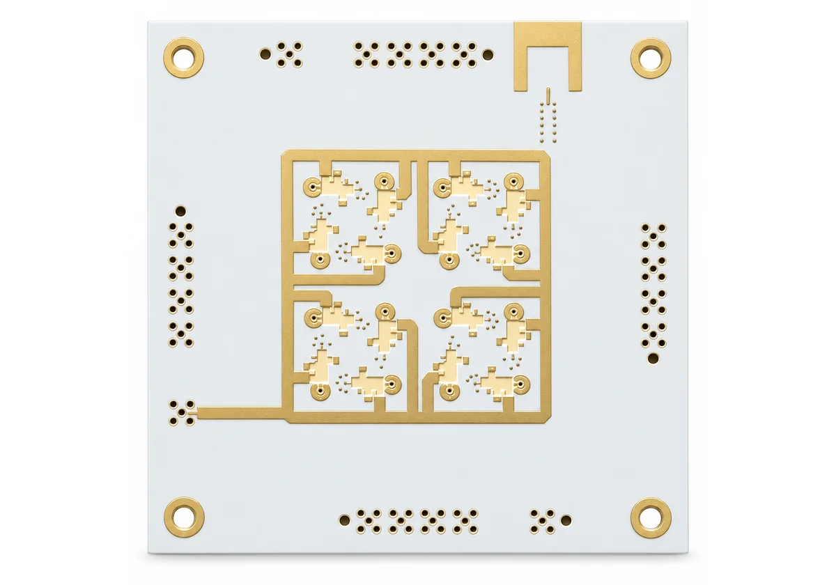
What is RT/duroid 5880
What is Rogers RT/duroid 5880?
Rogers RT/duroid 5880 is a glass-microfiber-reinforced PTFE laminate with a dielectric constant of 2.20 ± 0.02 and a dissipation factor of 0.0009 at 10 GHz. Often written RT duroid 5880 or simply Rogers 5880, it has the lowest electrical loss of Rogers’ reinforced PTFE materials, and its randomly oriented microfibers keep Dk uniform from panel to panel and across frequency.
That combination makes 5880 a default choice for Ku-band and above: airborne broadband antennas, military radar, missile guidance, point-to-point radio and millimeter-wave circuits. It is a PTFE material, so it needs PTFE-specific drilling, hole preparation and lamination, which we run as a dedicated process.
Properties
RT duroid 5880 typical properties.
| Property | RT/duroid 5880 | Condition / method |
|---|---|---|
| Dielectric constant (process) | 2.20 ± 0.02 | 10 GHz, IPC-TM-650 2.5.5.5 |
| Dielectric constant (design) | 2.20 | 8–40 GHz, differential phase length |
| Dissipation factor | 0.0004 / 0.0009 | 1 MHz / 10 GHz |
| Thermal coefficient of Dk | −125 ppm/°C | −50 to 150 °C |
| Moisture absorption | 0.02% | ASTM D570 |
| Thermal conductivity | 0.20 W/m·K | 80 °C, ASTM C518 |
| CTE (X / Y / Z) | 31 / 48 / 237 ppm/°C | 0–100 °C |
| Td | 500 °C | TGA |
| Density | 2.2 g/cm³ | ASTM D792 |
| Copper peel | 5.5 N/mm (31.2 pli) | 1 oz ED, after solder float |
| Flammability | UL 94 V-0 |
Thicknesses
Standard RT/duroid 5880 thicknesses.
| Thickness | Tolerance | Typical use |
|---|---|---|
| 0.127 mm (0.005″) | ± 0.0005″ | mmWave, thin multilayer RF |
| 0.252 mm (0.010″) | ± 0.0007″ | 24–77 GHz antennas |
| 0.508 mm (0.020″) | ± 0.0015″ | X/Ku-band antennas and filters |
| 0.787 mm (0.031″) | ± 0.0020″ | Lower-frequency antennas, wider lines |
| 1.575 mm (0.062″) | ± 0.0030″ | Rigid single-layer RF boards |
Because Dk is low, 50 Ω lines on 5880 are wider than on RO4350B or FR-4 at the same dielectric thickness. That lowers conductor loss and loosens etch tolerance, but uses more board area. Use the impedance calculator with Dk 2.20 for a first estimate, then we confirm with a field solver on your stack-up.
When to use
When Rogers 5880 is the right laminate.
Choose 5880 when loss and Dk stability matter more than cost: millimeter-wave antennas and feed networks, phased arrays, satellite and airborne communications, radar front ends and test fixtures above about 20 GHz. Below roughly 10 GHz, a hydrocarbon laminate such as RO4003C or RO4350B usually gives enough performance at lower cost and with FR-4-style processing.
Fabrication
Fabricating RT/duroid 5880 boards.
PTFE is soft and chemically inert, so 5880 is not processed like FR-4. Drilling uses dedicated parameters to avoid smear and burrs; hole walls are activated by plasma or sodium etch before plating, because PTFE will not take copper otherwise. The material moves more than glass-epoxy, so we scale artwork for dimensional change and control handling to avoid stretching thin cores.
Copper choice also matters: rolled copper gives the smoothest surface and lowest conductor loss at mmWave frequencies. Finishes are chosen for the application, typically immersion silver or ENIG for RF, with attention to nickel loss at high frequency.
- PTFE-specific drill parameters and deburring
- Plasma or sodium-etch hole activation before plating
- Artwork scaling for dimensional stability
- Rolled or reverse-treated copper for low conductor loss
- Finish chosen for frequency (immersion silver, ENIG, ENEPIG)
Hybrid stack-ups
Hybrid 5880 / FR-4 stack-ups.
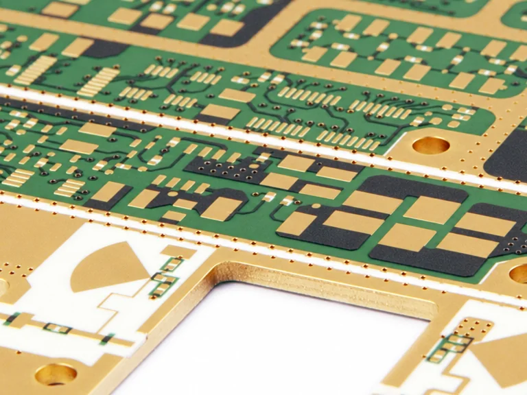
Many designs use 5880 only where the RF signal runs, with FR-4 or high-Tg FR-4 for digital, power and mechanical thickness. This keeps PTFE cost to one or two layers. The materials laminate at different conditions and expand differently, so the bonding film, lamination cycle and via structure are planned together. We return the hybrid stack-up with your quote. See PTFE / Teflon PCB for hybrid construction rules.
| Layer | Material | Use |
|---|---|---|
| L1–L2 | RT/duroid 5880 core | Antenna / RF feed |
| Bond | Low-loss bonding film or prepreg | Bond RF core to FR-4 |
| L3–Ln | High-Tg FR-4 | Digital, power, control |
5880 vs 5870 vs RO4003C
Rogers 5880 vs 5870 vs RO4003C.
| Laminate | Dk @ 10 GHz | Df @ 10 GHz | Processing | Positioning |
|---|---|---|---|---|
| RT/duroid 5880 | 2.20 ± 0.02 | 0.0009 | PTFE process | Lowest loss, mmWave |
| RT/duroid 5870 | 2.33 ± 0.02 | 0.0012 | PTFE process | Slightly higher Dk, very low loss |
| RO4003C | 3.38 ± 0.05 | 0.0027 | FR-4-like | Cost-effective RF to ~10–20 GHz |
| RO4350B | 3.48 ± 0.05 | 0.0037 | FR-4-like | The RF default |
RFQ
What to include in a Rogers 5880 RFQ.
- Laminate name and grade exactly as on your drawing, or “or equivalent” if substitution is allowed
- RT/duroid 5880 dielectric thickness and copper type (ED, reverse-treated or rolled)
- Frequency band and loss budget
- Hybrid layers and bonding material if any
- Layer count, finished thickness and tolerance
- Impedance targets and reference layers
- IPC class, quantity and schedule
FAQ
Material questions.
What is the dielectric constant of Rogers 5880?
2.20 ± 0.02 at 10 GHz (process Dk), with a design Dk of 2.20 from 8 to 40 GHz.
What is the loss tangent of RT/duroid 5880?
0.0009 at 10 GHz and 0.0004 at 1 MHz.
What is the difference between RT/duroid 5880 and 5870?
5870 has a Dk of 2.33 and Df of 0.0012 at 10 GHz; 5880 has Dk 2.20 and Df 0.0009. 5880 is the lower-loss option.
Is Rogers 5880 lead-free compatible?
Yes, the data sheet lists it as lead-free process compatible, with a Td of 500 °C.
Can Rogers 5880 be used in a multilayer board?
Yes, usually as a hybrid with FR-4 or high-Tg FR-4 layers bonded with a compatible film or prepreg.
Do you stock RT/duroid 5880?
Common thicknesses are usually available; stock and lead time are confirmed at quote.
Ready when your files are
Send your stack-up for a material check.
Upload Gerber, ODB++ or IPC-2581 data. Every quote includes a written engineering DFM review, typically within one business day.