
Rogers RO4003C PCB laminate
Rogers 4003C PCB: Lowest-Loss RO4000 Laminate
Rogers RO4003C: Dk 3.38 and Df 0.0027 at 10 GHz, about 25% lower loss than RO4350B, with FR-4-compatible processing for antenna feeds, filters and LNA matching.
- Dk @ 10 GHz
- 3.38 ±0.05
- Df @ 10 GHz
- 0.0027
- Lower loss vs 4350B
- ≈25%
- Compatible process
- FR-4
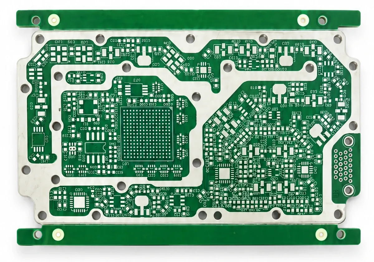
Overview
What is Rogers RO4003C?
Rogers RO4003C is a glass-reinforced hydrocarbon/ceramic laminate with Dk 3.38 ±0.05 and Df 0.0027 at 10 GHz. It is the lowest-loss member of the RO4000 family and still processes on standard FR-4 equipment. Designers choose it when loss matters more than material cost: antenna feeds, filter banks, LNA matching and precision couplers.
The practical question is usually “4003C or 4350B?” The answer comes from your link budget, trace lengths and whether you need UL 94 V-0.

Electrical properties
RO4003C electrical properties.
| Property | Typical value |
|---|---|
| Dk @ 10 GHz | 3.38 ±0.05 |
| Df @ 10 GHz | 0.0027 |
| TCDk | +40 ppm/°C |
| Dk stability 1–50 GHz | Within about 2% |
| Moisture absorption | ≈ 0.06% |
| Flammability | Not UL 94 V-0 rated |
Dk 3.38 stays stable across temperature and frequency, and low moisture absorption keeps it stable through humidity cycling, which matters for outdoor and automotive hardware. The lower Dk compared with FR-4 (4.0–4.5) gives wider traces for a given impedance, which cuts resistive loss and reduces sensitivity to etch tolerance.
4003C vs 4350B
Rogers 4003C vs 4350B.
| RO4003C | RO4350B | |
|---|---|---|
| Dk @ 10 GHz | 3.38 | 3.48 |
| Df @ 10 GHz | 0.0027 | 0.0037 |
| UL 94 V-0 | No | Yes |
| Thickness range | Fewer standard cores | Wider range, more stock |
| Cost | Higher | Lower |
| Best for | LNA, long feeds, cascaded filters | Most 1–20 GHz designs |
The 0.001 Df difference is worth about 0.1–0.2 dB per inch less insertion loss at 10 GHz. Specify 4003C when link-budget analysis shows that margin is needed for noise figure, gain flatness or output power. Otherwise RO4350B is usually the better-value choice.
Loss example
A worked loss example.
For a 6-inch microstrip feed at 10 GHz, the dielectric-loss difference between 4003C and 4350B is about 0.6–1.2 dB. In a receiver front end that can be a meaningful share of the noise-figure budget. In a 0.5-inch interconnect it is negligible. Copper roughness, connector launches and via transitions often matter as much, so look at the full chain before upgrading material.
Applications
Where RO4003C is used.
Point-to-point radio
IF and RF stages.
Test & measurement
Instrument RF sections.
Fabrication
Fabricating RO4003C.
Like 4350B, RO4003C processes on standard FR-4 equipment with no special drilling, plating or handling. We build all-Rogers and hybrid stack-ups, with impedance to ±8% verified by TDR. In hybrids, bonding material and lamination profile are chosen for both laminates, and CTE mismatch is reviewed during DFM.
- Standard mechanical drilling
- Standard copper plating
- Compatible bondply or prepreg for multilayer
- TDR coupons on each panel
Thicknesses
Standard RO4003C thicknesses.
| Core (mil) | ≈ mm |
|---|---|
| 8 | 0.203 |
| 12 | 0.305 |
| 20 | 0.508 |
| 32 | 0.813 |
| 60 | 1.524 |
Hybrid stack-up
Example RO4003C hybrid stack-up.
| Layer | Material | Use |
|---|---|---|
| L1 | RO4003C core (20 mil) | RF microstrip, antenna feed |
| L2 | Copper | RF ground reference |
| Bond | Compatible prepreg / bondply | Joins RF and FR-4 |
| L3–L4 | High-Tg FR-4 core | Digital, power, control |
| L5–L6 | High-Tg FR-4 | Routing and bottom components |
Putting only the RF layer on 4003C keeps most of the low-loss benefit while cutting material cost significantly. The critical points are bond-line thickness under the RF ground, CTE mismatch between the materials during lamination and reflow, and drilling through mixed materials. We plan the press profile for both laminates and microsection the bond line on coupons.
Design notes
Design notes for RO4003C.
Use the design Dk recommended by Rogers for your structure (often slightly higher than the process Dk of 3.38) when you calculate microstrip width. The lower Dk compared with FR-4 widens 50 Ω traces, which lowers conductor loss and makes the line less sensitive to etch variation, but it also takes more board area.
Above about 5 GHz, surface finish and copper roughness start to rival dielectric loss. Specify immersion silver or ENEPIG instead of ENIG for the RF layer, and request low-profile copper where the datasheet offers it. Keep a continuous ground directly under the RF layer and add via fences along long feeds.
- Use design Dk for width calculation
- Prefer immersion silver / ENEPIG above ~5 GHz
- Request low-profile copper for lowest loss
- Keep RF ground continuous; add via fences
Cost
Cost considerations.
RO4003C costs more than RO4350B per sheet and has fewer standard thicknesses in stock, so it can add lead time on non-standard cores. Using it only on the RF layer of a hybrid stack-up captures most of the benefit. If your design is not loss-limited, 4350B is usually the better choice, and you can ask us to quote both so you can compare.
RFQ
How to specify RO4003C.
- Name RO4003C and core thickness
- Impedance targets and frequency
- Hybrid layers and FR-4 grade, if any
- Finish (immersion silver or ENEPIG above ~5 GHz)
- Whether 4350B substitution is acceptable
FAQ
Material questions.
What is the Dk and Df of Rogers 4003C?
Dk 3.38 ±0.05 and Df 0.0027 at 10 GHz.
When should I choose 4003C over 4350B?
When link-budget analysis shows the extra 0.1–0.2 dB/inch matters, for example in LNA front ends, long feeds or cascaded filters.
Is RO4003C flame-rated?
RO4003C is not UL 94 V-0 rated; RO4350B is. Choose 4350B where V-0 is required.
What thicknesses are available for 4003C?
Common cores are 8, 12, 20, 32 and 60 mil; availability is confirmed at quote.
Can 4003C be processed like FR-4?
Yes, it uses standard drilling, plating and lamination.
Can 4003C be used in a hybrid stack-up?
Yes, RF layers on 4003C can be bonded to FR-4 digital layers with compatible bonding materials.
Ready when your files are
Send your stack-up for a material check.
Upload Gerber, ODB++ or IPC-2581 data. Every quote includes a written engineering DFM review, typically within one business day.