
Taconic (AGC) PTFE laminates
Taconic PCB: TLY-5 and RF-35 PTFE Laminates
Taconic, now part of AGC, makes woven-glass PTFE laminates for RF and microwave: TLY-5 (Dk 2.20, Df 0.0009 at 10 GHz) for mmWave and automotive radar, and the RF-35 family (Dk 3.5) for amplifiers, filters and antennas.
- TLY-5 Dk @ 10 GHz
- 2.20
- TLY-5 Df @ 10 GHz
- 0.0009
- RF-35 family Dk
- 3.5
- UL 94
- V-0
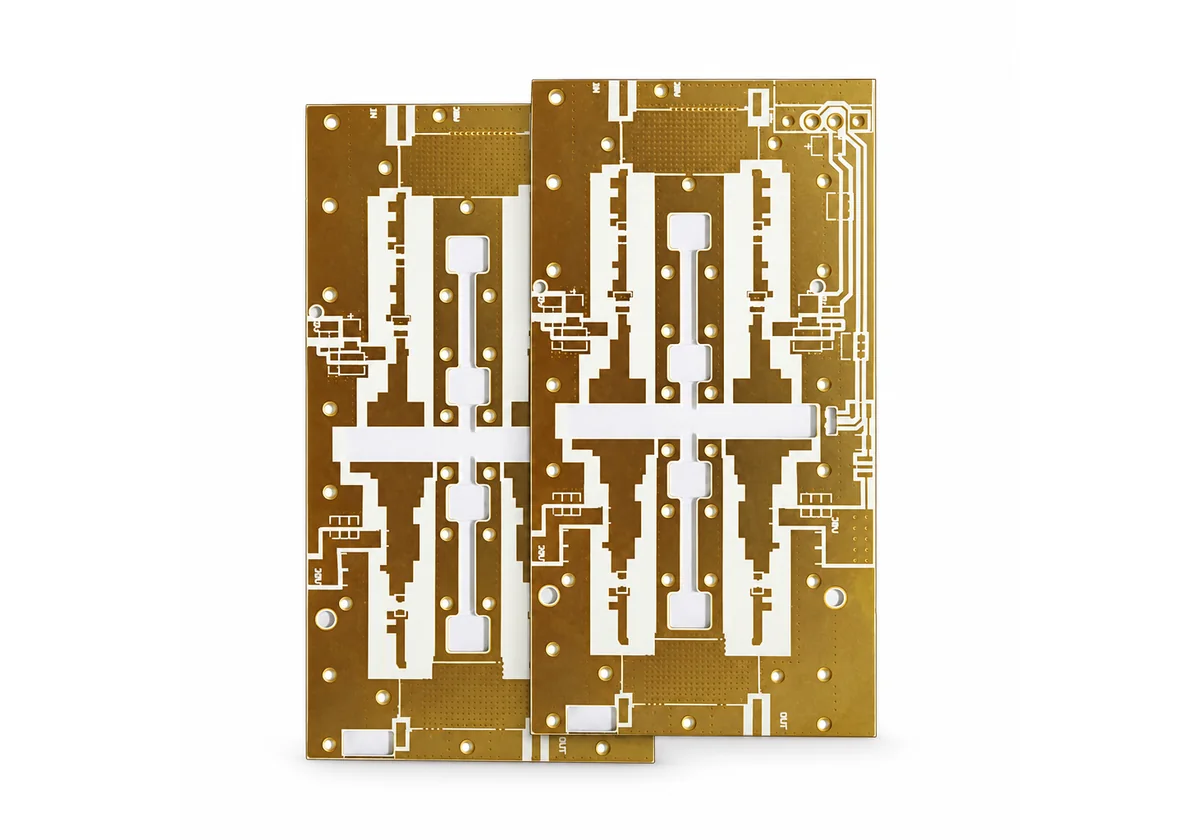
What is Taconic
What is a Taconic PCB?
A Taconic PCB is built on PTFE laminates from Taconic, now AGC Multi Material. The two most specified families are TLY, a lightly reinforced woven-glass PTFE with Dk 2.17–2.40, and RF-35, a ceramic-filled, woven-glass PTFE with Dk 3.5. Both are low loss, low moisture and UL 94 V-0.
Taconic laminates are common in automotive radar, satellite and cellular communications, power amplifiers and antennas. They are a frequent alternative to Rogers PTFE materials, and the choice usually comes down to the exact Dk, loss, stock and the material qualified on a program.
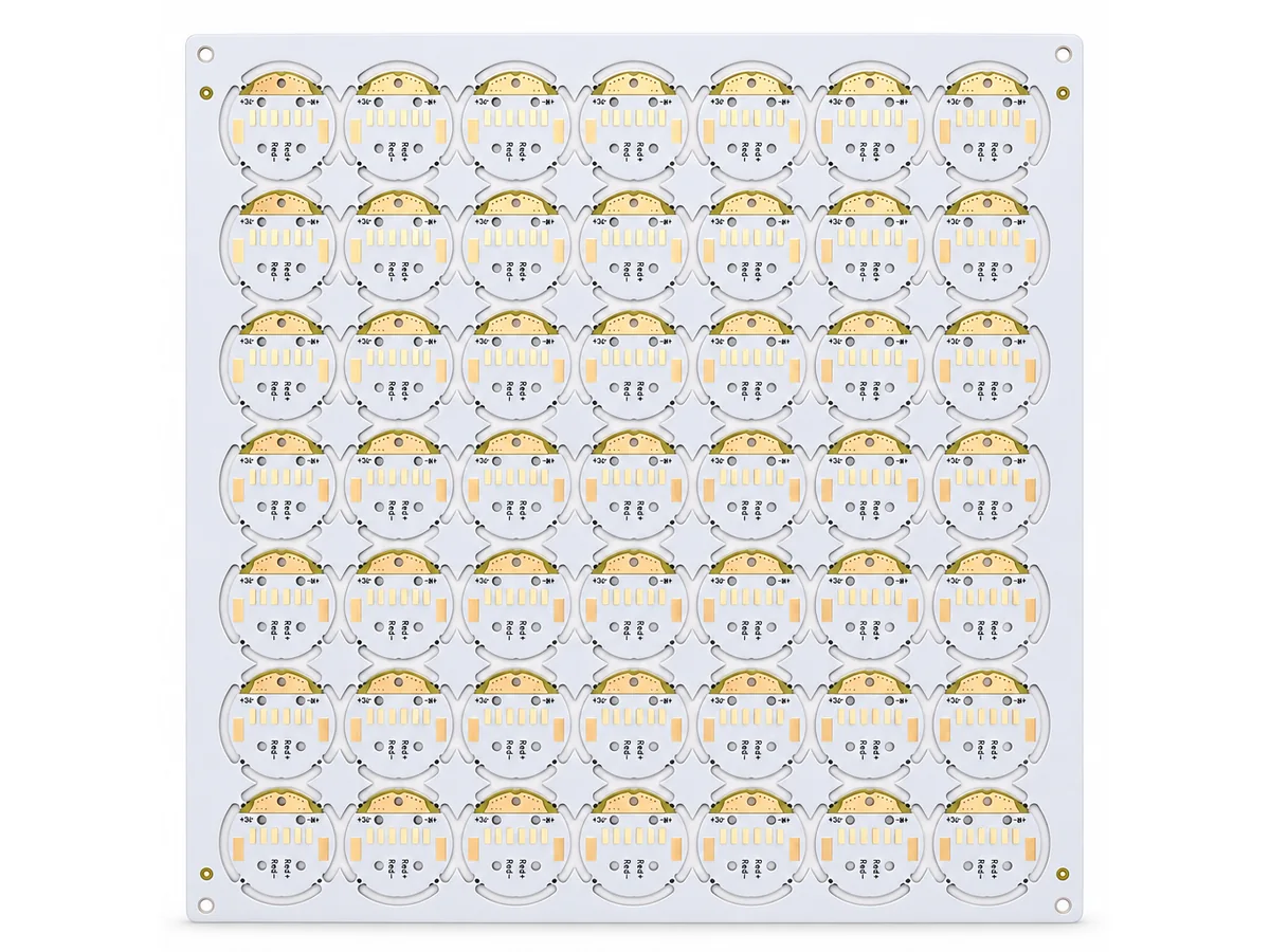
TLY family
Taconic TLY-5 and the TLY family.
| Property (TLY-5) | Typical value | Method |
|---|---|---|
| Dk @ 10 GHz | 2.20 | IPC-TM-650 2.5.5.5 |
| Df @ 10 GHz | 0.0009 | IPC-TM-650 2.5.5.5 |
| Moisture absorption | 0.02% | IPC-TM-650 2.6.2.1 |
| Thermal conductivity | 0.22 W/m·K | ASTM F433 |
| CTE x / y / z (25–260 °C) | 26 / 15 / 217 ppm/°C | ASTM D3386 |
| Peel strength, 1 oz C1 copper | 3.04 N/mm (17 lb/in) | IPC-TM-650 2.4.8 |
| Dielectric breakdown | > 45 kV | IPC-TM-650 2.5.6 |
| NASA outgassing TML / CVCM | 0.01% / 0.01% | |
| Flammability | UL 94 V-0 |
| Grade | Dk | Note |
|---|---|---|
| TLY-5A | 2.17 | Lowest Dk |
| TLY-5 | 2.20 | Most common; 77 GHz radar |
| TLY-3 | 2.33 | |
| TLY-3FF | 2.33 | Highly flexible, for curved antennas |
TLY-5 is designed for 77 GHz automotive radar and other mmWave antennas. Its light woven reinforcement gives dimensional stability for volume manufacturing while keeping Df near 0.0009.
RF-35 family
Taconic RF-35 and RF-35TC.
RF-35 is a ceramic-filled, woven-glass PTFE laminate with a Dk of 3.5, used for low-cost, high-volume commercial microwave: power amplifiers, filters, couplers and antennas. RF-35TC is the thermally conductive version for high-power designs where the substrate must spread heat from transmission lines and components.
| Property (RF-35TC) | Typical value | Method |
|---|---|---|
| Dk @ 10 GHz | 3.5 ± 0.05 | IPC-TM-650 2.5.5.5.1 (mod.) |
| Df @ 10 GHz | 0.002 | IPC-TM-650 2.5.5.5.1 (mod.) |
| Thermal conductivity (C1/C1, 125 °C) | 0.92 W/m·K | ASTM F433 |
| Moisture absorption | 0.05% | IPC-TM-650 2.6.2.1 |
| Density | 2.35 g/cm³ | IPC-TM-650 2.3.5 |
| Flammability | UL 94 V-0 |
When to use
When to choose a Taconic laminate.
Choose TLY-5 for mmWave antennas and radar where you want Dk 2.20 with very low loss, especially when the program already qualifies Taconic. Choose RF-35 or RF-35TC for amplifiers, filters and couplers at higher Dk, where smaller circuit dimensions and, for RF-35TC, better heat spreading matter. For lower-frequency RF that should process like FR-4, a hydrocarbon laminate such as RO4350B is usually cheaper.
Fabrication
Fabricating Taconic PTFE boards.
Taconic laminates are PTFE-based and need the same controlled process as other PTFE materials: dedicated drill parameters, plasma or sodium-etch hole activation before plating, artwork scaling for dimensional movement and careful handling of thin cores. Hybrid stack-ups with FR-4 are possible with the right bonding film and lamination cycle; we plan them with your quote. See PTFE / Teflon PCB for details.
- PTFE drill parameters and deburring
- Plasma or sodium-etch hole activation
- Artwork scaling
- Finish chosen for frequency
- Hybrid bonding planned in the stack-up
Taconic vs Rogers
Taconic vs Rogers PTFE laminates.
| Need | Taconic option | Rogers option |
|---|---|---|
| Dk 2.2, lowest loss | TLY-5 | RT/duroid 5880 |
| Dk ≈ 3.0, 77 GHz radar | — | RO3003 (Dk 3.00, Df 0.0010) |
| Dk 3.5, amplifiers and filters | RF-35 / RF-35TC | RO3035 (Dk 3.50, Df 0.0015) |
Taconic and Rogers make overlapping PTFE materials. If your drawing names one, we build on it. If it allows an equivalent, we compare Dk, loss, stock and lead time and propose an alternative only in writing.
RFQ
What to include in a Taconic RFQ.
- Laminate name and grade exactly as on your drawing, or “or equivalent” if substitution is allowed
- Taconic grade (e.g. TLY-5, RF-35, RF-35TC), dielectric thickness and copper type
- Frequency band and loss budget
- Hybrid layers and bonding material if any
- Layer count, finished thickness and tolerance
- Impedance targets and reference layers
- IPC class, quantity and schedule
FAQ
Material questions.
What is the dielectric constant of Taconic TLY-5?
2.20 at 10 GHz, with a Df of 0.0009.
What is Taconic RF-35 used for?
Low-cost, high-volume commercial microwave: power amplifiers, filters, couplers and antennas, at a Dk of 3.5.
Is Taconic part of AGC?
Yes. Taconic’s advanced materials business is now AGC Multi Material, and the products keep the Taconic names.
Taconic vs Rogers: which should I use?
Use the material your program has qualified. Otherwise compare Dk, loss, stock and lead time; TLY-5 and RT/duroid 5880 are both Dk 2.2 options.
Can Taconic laminates be used in hybrid stack-ups?
Yes, bonded to FR-4 layers with a compatible film or prepreg and a controlled lamination cycle.
Do you stock Taconic laminates?
Common grades and thicknesses are usually available; stock and lead time are confirmed at quote.
Ready when your files are
Send your stack-up for a material check.
Upload Gerber, ODB++ or IPC-2581 data. Every quote includes a written engineering DFM review, typically within one business day.