
Battery management system PCB
Battery Management System PCB: Design & Manufacturing Guide
Design and build guidance for BMS boards in EVs, energy storage and portable devices: cell monitoring isolation, 100 A+ current paths, thermal and automotive reliability.
- Stack voltage
- 400 V+
- Pack current
- 100 A+
- Power copper
- 2–6 oz
- Automotive range
- -40…+125 °C
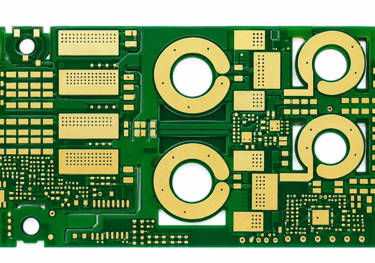
Isolation
Cell monitoring and isolation.
A battery management system PCB measures every cell to millivolt accuracy while isolating stack voltages of 400 V or more from low-voltage communications. Creepage and clearance follow IEC 60664 or UL 840, using routed slots where layouts are compact.
Current paths
Heavy copper for pack current.
Pack current flows through MOSFETs, shunts and fuses on the board. A 100 A pack needs 2–6 oz power copper, wide pours and even current distribution. See heavy copper and the trace width calculator.
Thermal
Thermal management.
- Thermal vias under MOSFETs, shunts and balancing resistors
- Copper planes to spread heat
- Heatsink or chassis mounting with TIM
- Consider metal core for concentrated heat
Automotive
Automotive BMS requirements.
- -40 °C to +125 °C operation, ISO 16750 vibration
- High-Tg laminate such as Isola 370HR
- IPC Class 3 and PPAP — automotive PCB
Architectures
BMS architectures and their boards.
| Architecture | Boards | PCB focus |
|---|---|---|
| Centralized | One board, all cell wires | Isolation, long sense harness, connector density |
| Modular / master-slave | Cell-monitoring slaves + master | Isolated daisy-chain comms, repeatable modules |
| Distributed | Small board per module or cell group | Compact, low-cost, high volume |
| Wireless BMS | Cell boards with RF links | RF layout, antenna, low-power design |
Architecture decides how many boards you build and what each must do. Modular master-slave designs dominate EV packs; distributed and wireless designs reduce harness weight but move complexity into the boards.
Measurement accuracy
Layout for accurate cell measurement.
Cell-voltage accuracy depends as much on layout as on the monitor IC. Route sense lines as Kelvin connections from the cell tabs, away from balancing and switching currents, and filter them close to the IC. Keep the analog front end over a quiet reference, and separate high-current return paths from measurement grounds. Current-shunt sense lines need the same Kelvin treatment, with symmetric routing to the amplifier.
- Kelvin-connect cell and shunt sense lines
- Filter sense lines at the IC
- Separate measurement ground from power return
- Keep balancing resistors away from the AFE thermally
Test
Testing BMS boards.
Beyond electrical test of the bare board, assembled BMS boards are typically checked with hi-pot isolation tests between high- and low-voltage domains, functional tests that simulate cell voltages and balancing, and calibration of measurement channels. We can run customer test procedures on assembled boards; see PCB assembly.
Standards
Standards that commonly apply to BMS boards.
| Standard | Scope |
|---|---|
| IEC 60664 / UL 840 | Insulation coordination, creepage and clearance |
| IEC 62619 / UL 1973 | Safety of industrial / stationary batteries |
| ISO 26262 | Functional safety for automotive systems |
| ISO 16750 | Automotive environmental conditions |
| IPC-2221 | General PCB design spacing |
Board-level choices such as spacing, slots, laminate CTI, coating and test voltage follow from these standards. Tell us which ones apply so DFM can check the board against them.
Assembly
Assembling BMS boards.
BMS assembly combines fine-pitch monitor ICs, isolators and microcontrollers with heavy-copper power paths and large connectors. Heavy copper sinks heat during reflow, so profiles and thermal reliefs are planned to solder both fine-pitch and power joints well. Conformal coating is common for high-voltage reliability, with masking around connectors and test points. See turnkey PCB assembly.
Balancing
Passive vs active balancing on the PCB.
Passive balancing burns excess charge in resistors, which is simple and cheap but puts heat on the board right next to the measurement circuits. Active balancing moves charge between cells with inductors or transformers, which is more efficient but adds magnetics, switching nodes and EMI to the layout. Either way, plan copper area and thermal relief for the balancing current, and keep it away from the analog front end.
| Passive | Active | |
|---|---|---|
| Board heat | Higher (resistors) | Lower |
| Complexity | Low | Higher (magnetics, switching) |
| Layout risk | Thermal near AFE | EMI and switching loops |
Coating
Conformal coating for BMS boards.
High-voltage BMS boards are usually conformally coated to keep moisture, dust and electrolyte vapour from reducing surface insulation. Acrylic, silicone and polyurethane coatings are common, applied by spray or selective coating with connectors and test points masked. Coating thickness and coverage are inspected under UV. Specify the coating type and keep-out areas on the assembly drawing.
Energy storage
Energy storage BMS.
Grid and commercial ESS BMS boards monitor hundreds of cells, carry higher currents and need larger creepage distances. Heavier copper and larger formats are common. Overview: BMS & power electronics PCB.
FAQ
Common questions.
What copper weight do BMS PCBs use?
Typically 2–6 oz on power paths and 1 oz on signal layers.
How is isolation achieved?
Creepage/clearance per IEC 60664 or UL 840, routed slots, high-CTI laminate and hi-pot test.
Which BMS architecture should I choose?
Master-slave modular designs are most common in EVs; centralized suits small packs; distributed and wireless designs cut harness weight.
How do I keep cell measurements accurate?
Kelvin-route sense lines, filter at the IC, and keep measurement grounds away from switching and balancing currents.
Do you test BMS boards?
Yes: electrical test, hi-pot isolation and customer functional tests on assembled boards.
What laminate do automotive BMS boards use?
Typically high-Tg, CAF-resistant FR-4 such as Isola 370HR.
Ready when your files are
Send your design for an engineering review.
Upload Gerber, ODB++ or IPC-2581 data. Every quote includes a written engineering DFM review, typically within one business day.